Rec-IgnitionAssembly
The are two different variants of Rec-Ignition. One is for digital
inputs like points or Dyna hall effect inputs. The are characterized by
the inputs being pulled to ground and then released for the spark. The
2nd is for analogue type inputs - pickup coils or reluctors. The same
circuit board is used for each but each is populated with components
differently
|
Digiplex version is the same as the analog with changes noted in table.
| Component | Digital Inputs | Analog Inputs | Digiplex | Analog Inputs MkII |
| R1, R2 | Link | 3k9 | R2 not used | 3k9 |
| C1, C2 | Link | 1uF | C2 not used | Link |
| C3, C5 | N/A | 0.01uF | C3 not used | 0.01uF |
| C6 | 0.1uF | 0.1uF | 0.1uF | 0.1uF |
| C7 | 10uF | 10uF | 10uF | 10uF |
| C8 | NA | 0.1uF | 0.1uF | 0.1uF |
| R3, R4 | 47k | 6k8 | R3 not used | 1uF |
| R5, R6 | 10k | 10k | 10k | 10k |
| R7, R8 | 3k9 | 3k9 | 3k9 | 3k9 |
| R9 | 10k | 10k | 10k | 10k |
| X1, X2 | NA | IN914 up | X1 not used | IN914 up and down |
| X3, X4 | 1k5 | IN914 up | X3 not used | NA |
| X5, X6 | IN914 up | 47k | X5 not used | 18k |
| X7, X8 | IN914 dn | 47k | X7 not used | 47k |
| T1, T2 | BC547 | BC547 | BC547 | BC547 |
| Q1, Q2 | PHP6N60E | PHP6N60E | PHP6N60E | PHP6N60E |
| U1 | 7805 | 7805 | 7805 | 7805 |
| U2 | Attiny26 | Attiny26 | Attiny26 | Attiny26 |
|
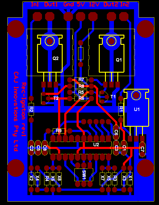
Click on the image below for an enlarged image
Assembly Steps
You may choose to solder the wires directly onto the circuit board rather than use the supplied terminals.
- Assemble and test the power supply
- Assemble and test the input conditioning
- Assemble and test the coil drivers
- Final assembly and testing
1. Assemble and test the power supply
Solder the IC socket and the 3 connectors at top.
Solder the components U1(the voltage regulator), C6, and C7 .Carefully noting
polarity.
Apply a supply voltage between the +12V terminal and Gnd
terminal. A 9V battery will work fine.Verify that 5V appears on the 5V
terminal.
2. Assemble and test the input conditioning
Solder components R1, R2, C1, C2, X1, X2, X3, X4, R3, R4, and the
other terminal blocks. Depending on which Rec-Ignition module you are
building, some of these components may be links or not used.
Apply supply voltage again.
For digital inputs verify 5V appears on pins 11 and 20 of U2 and on the 2 inputs on the terminal blocks.
For MkI analogue inputs verify 2.5V appears on pins 11 and 20 of U2. No voltage should appear on the 2 inputs on the terminal blocks.
For MkII analogue inputs verify 1.4V appears on pins 11 and 20 of U2. No voltage should appear on the 2 inputs on the terminal blocks.
3. Assemble and test the coil drivers
Solder the components R5, R6, R7, R8, T1 and T2.Then solder Q1 and Q2. Don't forget their heatsinks.
A dummy load like a 12V torch bulb will make the next steps easier.
Connect the bulb from the output terminal to the +12V terminal. This is
just like your coils on your bike.
Apply supply voltage again.
0V should be present of the gates of the FETs ( leftmost pin on the
diagram ).The bulb should be unlit. If you short pin 9 of U2 to ground
you should see the gate of Q2 rise to the supply voltage. The bulb
should light. Repeat this for pin 8 of U2 and Q1.
4. Final assembly and testing
Install the remaining components and U2. A 0.1uF cap is solder under the chip (underside) between pins 5 and 16.
Apply supply voltage again.
With the digital input version, you should be able to short the inputs to ground and see the corresponding output energised.
With the MkI analogue version, you should see 3.0V on C8/R9.
With the MkII analogue version, you should see 1.6V on C8/R9.
